Brittain Main. Positive Control System. Course and Heading. Altitude Control. Tidbits and Rules of Thumb. Parts Gallery.
Positive Control System
Operation Overview
The default condition of the Positive Control (PC) System is "always on".
As the vacuum system churns up, the pilot will be able to feel an increase in the force being required to rotate the controls left and right (aileron turn). (I suppose that a pilot with sensitive feet would also be able to ascertain a difference in force from the rudder pedals/rudder as well).
In my '66 E Mooney, the PC can be (a) disconnected/interrupted and (b) "superseded" by pilot inputs.
To disconnect or interrupt the PC system, the pilot pushes a small button (the cut-off valve) on the left handle of the pilots controls. This interrupts the vacuum to the PC system. When this button is engaged, the control forces needed to manipulate left and right turns (and up and down turns off as well if pitch control is installed) is significantly reduced.
Some pilot don't care for the PC system and have installed rubber bands or 35mm film canisters over the button to keep it depressed/engaged
Other pilots have simply removed the button in its entirety.
For those who keep the PC system in its natural state and always on, it takes a mild amount of force to overcome the PC system. After about (I'm guessing) 10 hours of flying with the PC system engaged, it becomes the new normal and flying other planes without this extra force seems strange).
The System
I don’t have all of the ins and outs of how the turn coordinator and/or gyroscope modify the vacuum to the system - at some point, I’ll remove this paragraph with updated text.
In general terms, the PC system consists of a set of pneumatic tubes (that hold a vacuum) and four “servos” (technically, these are vacuum pots and not servos, but everyone calls them servos, so I’ll do the same).
(It is important to note that there are several/many variations of the PC system as the system was improved through the years - through this document, I’ll refer to what my first hand knowledge is - but be warned that some parts are in the front of the airplane and some in the tail - based on the installation date)
As the airplane flies, it receives electric input from the turn coordinator and/or gyroscope - this electric input is transmitted to an actuator valve that opens/closes the differential vacuum to the left and right servo in the wings and the left and right rudder servo in the tail. If the gyroscope “feels” that the airplane is unbalanced to the left/port, it will increase the vacuum in the left wing to pull the aileron down to counteract the wing down.
Info from Vance Harral on the above paragraph:
You say, "As the airplane flies, it receives electric input from the turn coordinator and/or gyroscope - this electric input is transmitted to an actuator valve that opens/closes the differential vacuum to the left and right servo in the wings and the left and right rudder servo in the tail." You should double check me on this, but I believe the actuator valve has both mechanical and electrical inputs. The mechanical inputs are inherent to the TC itself, and the basic PC system will work without electricity. The reason the valve also has electrical inputs is, that's what allows an Accutrack/Accuflite/B-5/B-6 unit to drive turns for heading and course tracking. An airplane which only has the PC system and no Accutrack/Accuflite/B-5/B-6 has, I believe, no electrical connections to the actuator valve. The TC itself still has electrical connections, but that is only to keep the TC gyro turning in the event of a vacuum failure. In that sort of failure, you won't have PC, nor will you have vacuum-powered AI/DG gyros; but at least you'll still have a working TC whose gyro is being spun by an electric motor.
As the system is pneumatic, it does this frequently, incessantly, and smoothly - all so as the pilot feels the airplane correcting itself as it flies.
The Parts
The physical parts of the system include the servos and the hose.

Servos
The servos are relatively simple “pots” or “cans” that are covered by a flexible deep rubber diaphragm (this rubber has a plate and chain connected to it if is a aileron servo or a plate and cable if it is a rudder servo).
This rudder servo appears to have been recently re-taped.
When servos are re-taped, there is a specific procedure - and it involves using 3M 33+ tape (yes, that specific brand and style).
Technically, the servos are labeled with a part number of “BI 706”. In owning and reviewing several servos, I’ve discovered that about half of them do not have part numbers or labels stamped on them. I don’t know why, they just don’t.

Wing Servo Access
This photo shows the access panel location for the servos.
It does not show the second elbow that most who access this area wish that they had.

Hose
The hose for this portion of the system is either red or green (relatively rigid) Polyethylene Instrument Grade Tubing Type 1 Grade E5 (aka Poly-Flo). Red leads to and controls the left wing; Green leads to and controls the right wing (this is in my ‘66 E - mine may be backwards from Drawing 1703 Sh 8 of 16 and other airplanes).
Info from Vance Harral:
Regarding the color of the vacuum lines, it's certainly possible for an airplane or a manual to accidentally reverse the color scheme. But as you might guess, the intent is always for red hose on the port side and green on the starboard side, i.e. same color scheme as your position lights. For systems with altitude hold, there are yellow and blue tubes for up/down, and orange tubing for the reference chamber line. These are harder to remember because there is no position light analogue.
Instructions on use
For the PC, the instructions should be “to bypass the system” as the PC system is - by default - always on.
To bypass the system, press the button on the left-horn of the pilot’s yoke. As this button is pressed, the pilot should feel the greater ease to deflect the controls. Some pilots use the button to lighten forces when they are maneuvering to land. Personally, I’ve gotten used to the forces and I overpower them (this does not damage the PC system).
Additional information from Vance Harral in a DM:
In the page on Positive Control, you make reference to the PC disengage button on the yoke. There are two different implementations of this disengage, and it would be helpful to note the difference. As you know, PC is disabled by opening the vacuum system to ambient air, such that the lines have no pressure (vacuum), and therefore cannot actuate the servos. In older PC-equipped Mooneys (60s era, not sure of exact years), the yoke button is itself the physical dump mechanism. Vacuum lines run up into the yoke, and pressing the button ports them to ambient air. The button has an O-ring around it, which can crack, hence the advice to "check the yoke button O-ring" for cracks. In these airplanes, it is possible to pull the button all the way out of its socket, The reason is to facilitate replacing the O-ring, but doing so has the side effect of "permanently" disabling the PC. Doing so allows a continuous flow of unfiltered air into the system, which is arguably not good for it, but in practice is probably of little consequence.
In "newer" PC-equipped Mooneys (70s era), however, the PC disable button on the yoke is an electrical switch, not a physical vacuum dump port. Depressing the switch electrically actuates a vacuum relay under the instrument panel, which opens the system to ambient air. This design avoids the need to run vacuum tubes through the yoke shaft. But in these airplanes, there is no O-ring on the yoke button (that O-ring is in the vacuum relay, it can still crack). Importantly, you cannot pull this electrical switch button out of the yoke, except by physically damaging the switch, which is obviously not intended. To "permanently" disable PC, one must resort to putting a rubber band or film canister over the yoke, or wiring a second electrical switch into the system (arguably a minor mod, but not everyone who does this bothers with the legalities).
Anyway, most owners with one type of PC disconnect button are not aware the other type exists, and hence there is confusion over the advice to check O-rings and remove buttons.
System Check
Finding a logical, systematic method to check the PC system was a challenge.
Kerry McIntyre (www.knr-inc.com) has written several great Mooney-related articles. His Shop Talk Article titled “Are You Positive? (PC Systems)” is probably the best document out there on how to check your system.
There are two simple on-the-ground checks:
When taxiing, a turn (that causes the gyroscope to sense a same-wing down) should deflect the yoke in the opposite direction - a right turn should cause the yoke to turn left.
Another simple check - when on the ground (with engine and vacuum running) turn the centering knob on the yoke above the clock to the far left (counterclockwise) and the far right (clockwise). These turns should defect the yoke in the same direction of the knob’s turn.
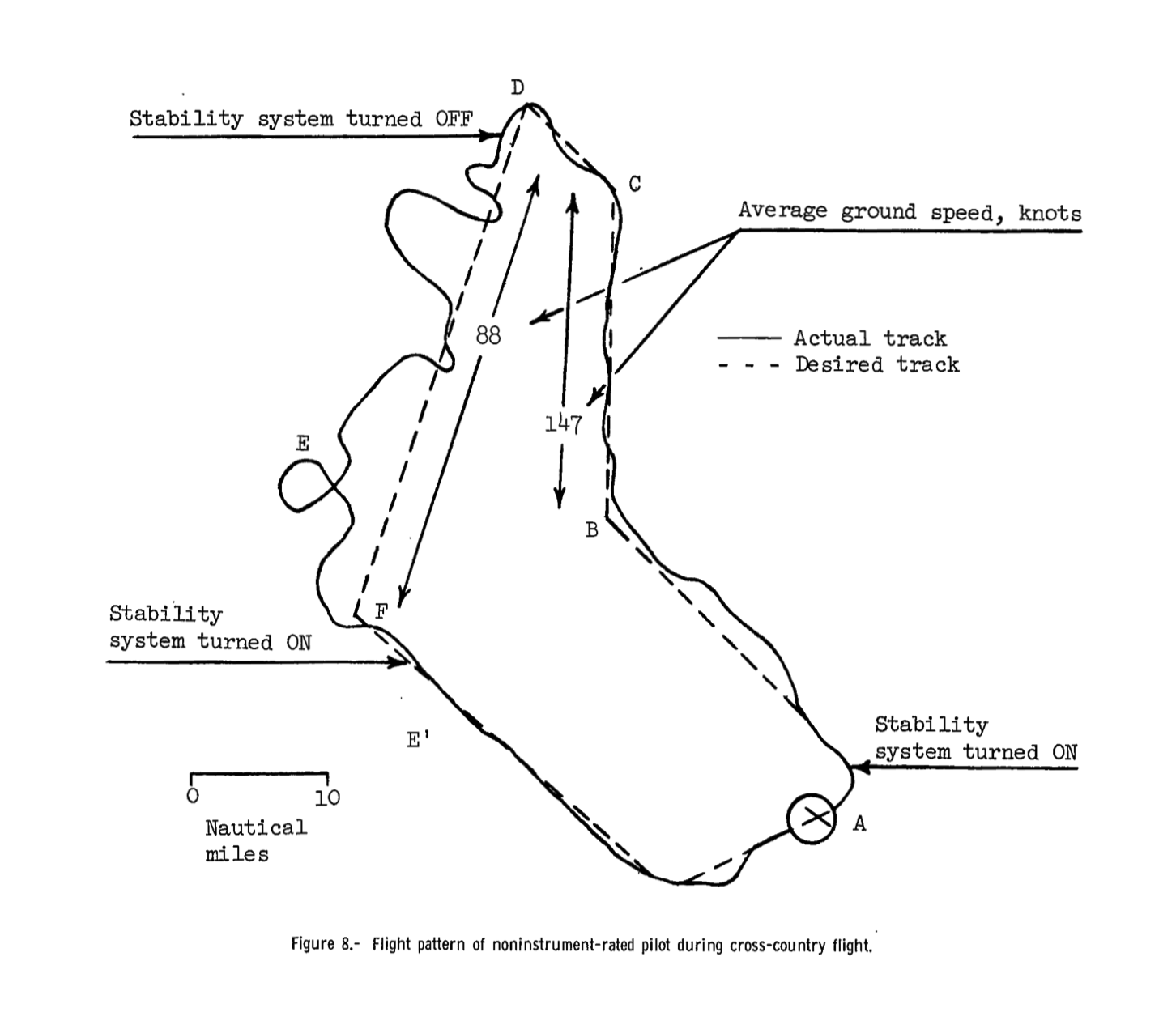
NASA Study
In May 1967, Norman R. Driscoll of the Langley Research Center authored a report titled “EFFECTS OF A SIMPLE STABILITY AUGMENTATION SYSTEM ON THE PERFORMANCE OF NON-INSTRUMENT-QUALIFIED LIGHT-AIRCRAFT PILOTS DURING INSTRUMENT FLIGHT”. The summary of the report is provided here, is profound, and pre-dates by several decades the “push for straight and level flight” button on many of 2020’s autopilots.
“Non-instrument-rated private pilots were not able to operate the basic aircraft (without lateral-stability augmentation) in instrument conditions, and also to perform limited navigation. With the aid of the lateral -stability augmentation system, the noninstrument-rated pilot was capable of sustained instrument flight and limited radio navigation. Flight could be performed in a sufficiently safe manner to permit recovery to visual flight conditions from an inadvertent instrument situation.”
A brief review of the graphic that tracks a VFR pilot’s attempt to follow a course when in IMC-like conditions (see below) should provide the Mooney owner (especially the VFR pilot) with a desire to get their PC system working.
Original US Patent for PC System

Patent 3,006,580 titled “Flight Control Means for Aircraft” by A. Clarkson filed February 9, 1959 and patent awarded October 31, 1961 is brilliant and worth a glance.
Here is the patent application.
References and Useful PDFs
Brittain’s document naming convention is probably logical, but I have yet to understand it. Below, I’ve listed the cover page names of their different PDFs related to the PC system:
Mooney "Positive Control" Operation & Service Instruction Manual No. 11968 (Issue D 5/30/01) - This is for A&P’s use to trouble shoot the PC system.
Mooney “Positive Control” Operation & Service Instructions Manual No. 11990 (Issue A 5/31/01) - This is also for A&P’s to use to trouble shoot the system. The documents have overlap, but are different.
Brittain Model LSA-2 Stability Augmentation System Installation Instructions 11971 for Mooney Model M20C S/N 3185 and Subsequent and Mooney Model M20E 832 and Subsequent - this includes the plans for the installation of the PC system.
References to Mooneyspace.com

Improperly Sealed Servos
From outermarker on Mooneyspace.com here.
The directions to properly taping a servo with 3M 33+ tape is on page 12 of this document.
On May 4, 2009, Seth initiated a topic about Brittain autopilots (that he commented on in 2012) noted this:
It's always fun to see an old thread be reborn. Especially since I originated the thread two years ago! Update: I sold my 1967 Mooney M20F and now have the 1983 Mooney M20J Missile 300. It's equipped with a KFC 150 system and I admit having an autopilot is amazing. It allows you to manage the flight. I hand flew my former F model accross the US from coast to coast, got my IFR Ticket, flew approaches to minimum in hard IFC with no autopilot, and now that I have one, I'd figure out a way to get a system into the old plane.
In fact, the new owner, who is a friend of mine, just purchased a Britain system and is looking to install it. I let him know for the functionality it is the best bang for the buck. I did a lot of research and I was planning to retrofit the aircraft with one of the Britain models. However, I would only reccomend doing so if your PC system is working properly. If your PC system is not working and you don't have the hardware, then plan on installing a newer system. Otherwise, if it's simply repair or overhaul, get it done. You won't regret it.
Hank provided this valuable insight regarding the autopilot system:
Many PC problems boil down to two things: either the hoses are old, cracked and/or missing; or the many connectors in the tubing lines are old, cracked and split. My tubing had all been replaced before I bought the plane, and the PC and Brittain systems worked great. A couple or three years later I was having issues, and had to replace the connectors in the tubing where it went through the firewall, split to go to both wings, split again to go to the static ports, etc. It was a very inexpensive fix, just like when I had an aileron servo rebuilt by Brittain.
It's a wonderful thing! I have both AccuTrak and AccuFlight, and love them both.
In a DM, Vance Harral noted:
Might be worth nothing that one way tubing becomes cracked or split is when people installing interior panels drive a screw right through the tubing, thinking they are connecting the screw into something "good", when they are in fact doing the opposite. This is the reason the PC system in our Mooney was not working when we first purchased it - someone had driven a baggage panel screw right into one of the vacuum lines, where they run down the port side of the fuselage.
211° wrote about checking the PC system:
In my searches, I’ve been quite surprised at the loss of vacuum in connection points. Especially the t’s in the baggage area.
As a check you can remove the t’s and insert the correct size outer diameter rubber or nylon tubing that matches the plastic (red and green) tubing’s inner diameter. Connect the hoses from the front to the wing hoses.
This also has the benefit of keeping (the highly probable leaking) rudder servos from the test.
Then go taxi the airplane. As you push the right rudder the turn coordinator should deflect and cause the ailerons and yoke to turn the opposite direction. (This should occur with or without the rudder hoses connected)
My Occam‘s razor list of most likely issues:
Thumb button - go to Home Depot and buy a pack of rubber washers for $5. Replace both washers on the thumb button. 30% chance that this will fix vacuum issues.
Rear/rudder servos. They’re behind the battery in a caustic location. Before contorting your body and scarring your head, remove them temporarily from the equation as noted above.
After you disconnect these lines, get a hand vacuum pump from Harbor Freight and try to vacuum the lines to 5 psi. With any luck after 20 or so pumps you’ll begin to see the rudder or aileron deflect. If it deflects and holds 5psi, smile as that part of the system checks out.
If all four lines check out, I would think that the T is leaking. When they’re off, try to plug two ends and suck on the third. These T’s always feel like they leak. I think that these T’s and the connectors are highly suspect in any system. (And relatively easy to swap out)
No need to try to test the red and green lines that run to the front as they’re connected to a filter and won’t seal.
If the wing servos lines don’t deflect. I’d look at these third. The boots are probably leaking. I ended up buying new servos as I couldn’t get them to seal well with re-taping. I don’t think that I have the knack.
Fourth the rudder servos. Same as wing servos but a different contorted challenge.
If you have altitude hold. It is separate from the green and red tube system but it does share and use the vacuum.
Right now, I can hold altitude or hold heading, but not both. I think that my altitude box in the back has a slow leak where a line should be plugged.
That minor leak has the benefit of making me wonder which part of the autopilot is better - heading hold or altitude hold. The PC system still works in altitude hold, so I frequently lean toward flying with that... unless I’m flying through falling pressure, at that point the airplane constantly tries to climb and needs resetting more frequently.
The implementation is pretty clever: it actually senses changes in airspeed and/or "G" load, and applies elevator to counteract them. I've attached a page from the NAV-FLITE II/B-5/B-7 Operating manual that describes the mechanism.